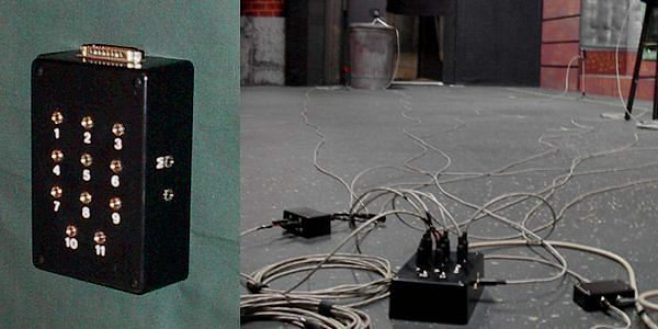
Analog to Digital Converter Console

The component level chip used for the analog to digital converter was the TLC1542. This chip features eleven separate analog inputs, and its own internal system clock. The output is a digital ten bit signal (1024 steps of resolution), between Vref- and Vref+, which are ground and +5v, respectively. So, the voltage input from each channel can be calculated, with resolution to 4.88 millivolts. That reading can then be sent to other device specific conversion methods, that will calculate the appropriate unit of measurement for that channel.
The A/D box communicates with the computer via the parallel port, which provides 8 usable write bits, and 5 usable read bits. Two read bits are used for the TLC1542's needed data and EOC lines, two of the other read bits are used for two separate binary inputs (for motion detectors), and the remaining bit is used as a box status, so the software can verify when the unit is plugged into the computer. Three of the write bits are used for the TLC1542's needed address, CS, and I/O system clock lines, while the other two are used as a power indicator, and the status box output. The other three write bits are left open, and could be used to trigger remote equipment (video/still cameras, audio recorders, etc.). The status box is merely a luxury, as it will trigger a small audible alarm and flashing LED when a substantial anomaly occurs.